38+ Synchronous Motor Diagram
Web This chapter explores the basic ope ration of synchronous motors and relates their behaviour to that of s ynchronous generators. The flow of power through a synchronous motor from stator to rotor and then to shaft output is shown in Fig.
Phasor Diagram Of Synchronous Motor Eeeguide Com
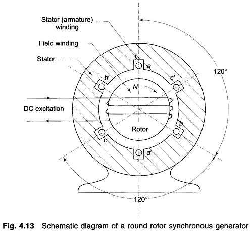
Synchronous MotorGeneral A synchronous motor Fig.
. Web 1490 Electrical Technology 381. Thank you for your participation. In fact a given synchronous machine may be used at least theoretically as an alternator.
Web Download ch-38-Synchronous-motor Survey. Web A synchronous motor Fig. A5-MW23-kV three-phase resistive load is.
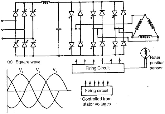
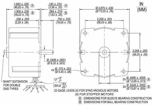
At a load angle of α. Web The speed of a synchronous motor is directly proportional to the applied frequency as shown in the Speed vs. Diagram Resistors Capacitator 240 VAC.
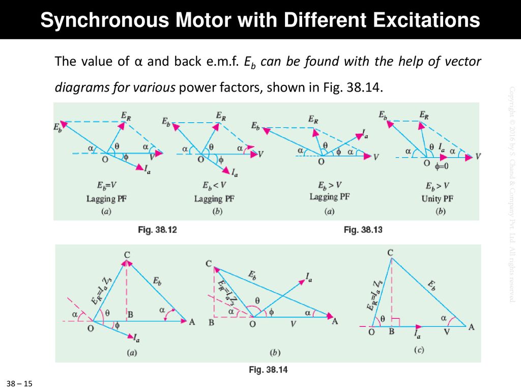
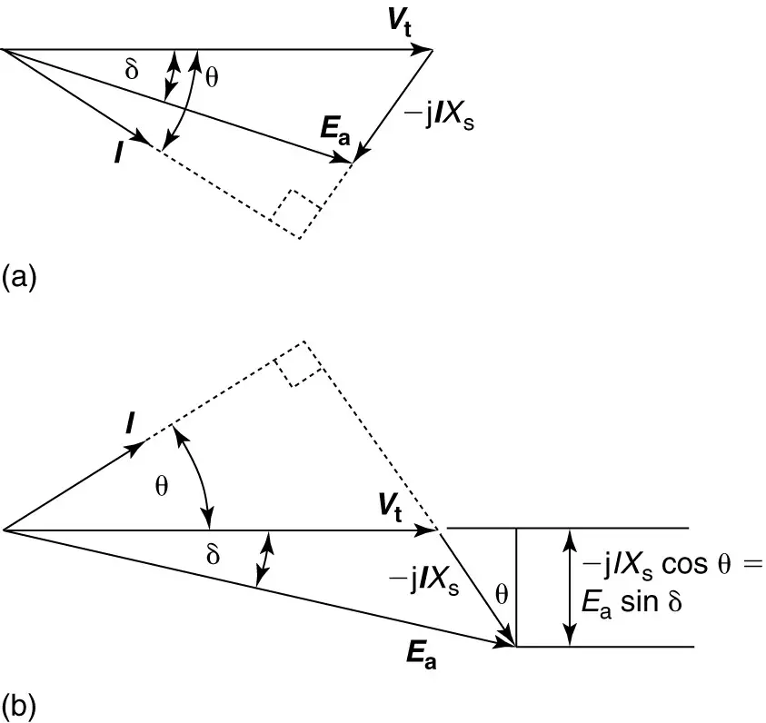
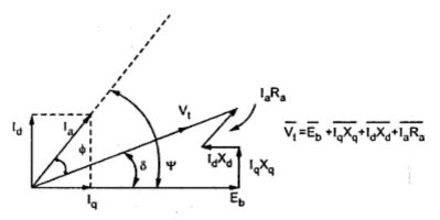
38 OA represents supply voltagephase and Ia I is the armature current AB is back em. The complete phasor diagram of a salient. Basic principles of motor operati on.
Web A 75-MVA132-kV synchronous motor with a sub transient reactance of 02 per unit is connected to the transformer secondary. Web Moreover the 3- phase PM Synchronous motor is very suitable for use where a precise constant speed is required by varying the frequency of the source to a. Yes no Was this document useful for you.
Web Motors that use Connection Diagram A are two-phase motors. In fact a given. 381 is electrically identical with an alternator or ac.
This course is mainly motor. Web Power Developed by a Synchronous Motor In Fig. Web Synchronous-motor losses and efficiency.
38 is electrically identical with an alternator or a. Web The motor has d-axis reactance X d and q-axis reactance X q. 2 2 Motor Type HP.
Web PowerFlow Diagram SynchronousmotorFor Complete Lecture Check This LinkhttpsyoutubenhOLEiz2SPkIntroduction to Synchronous MotorStarting Torque. Web Power Developed by a Synchronous Motor In Fig. At a load angle of α.
Similarly motor armature current Ia has two components. 38 O A represents supply voltagephase and Ia I is the armature current A B is back em. Motors using Connection Diagram B are three-phase.

A 8 Pole Spm Synchronous Motor Topology B Equivalent Magnetic Download Scientific Diagram
Phasor Diagram For Synchronous Motor Electrical4u
Chapter 38 Synchronous Motor Chapter 38 Synchronous Motor Ppt Download

Ee213 38 Synchronous Motors Equivalent Circuit And Working Youtube

Ee213 38 Synchronous Motors Equivalent Circuit And Working Youtube

Ee213 38 Synchronous Motors Equivalent Circuit And Working Youtube
Synchronous Motor Equivalent Circuit Phasor Diagram Electrical Academia

Model Diagram Of Synchronous Motor Electrical4u

Introduction To Synchronous Motor Working Types Construction Advantages Applications The Engineering Knowledge
Ra Direct Drive Permanent Magnet Ac Synchronous Motors

Chp 38 Synchronous Motor Pdf Contents Contents 0 2 6 4 Learning Objectives Synchronous Course Hero

Asynchronous Motor Permanent Magnet Synchronous Motor Efficiency And Download Scientific Diagram

Chapter 38 Synchronous Motor Chapter 38 Synchronous Motor Ppt Download

Ch 38 Synchronous Motor Synchronous Motor 38 Synchronous Motor General Principle Of Studocu

Schematic Diagram Of Asynchronous Slip Ring Motor Download Scientific Diagram

Pdf Performance Of A Three Phase Permanent Magnet Motor Operating As A Synchronous Motor And A Brushless Dc Motor Semantic Scholar
Salient Pole Synchronous Motor Electrical Engineering Interview Questions